
TK 51T-A2 PWM Driver Module 30Pin Inverter Welding Machine Control Board
₹499.00
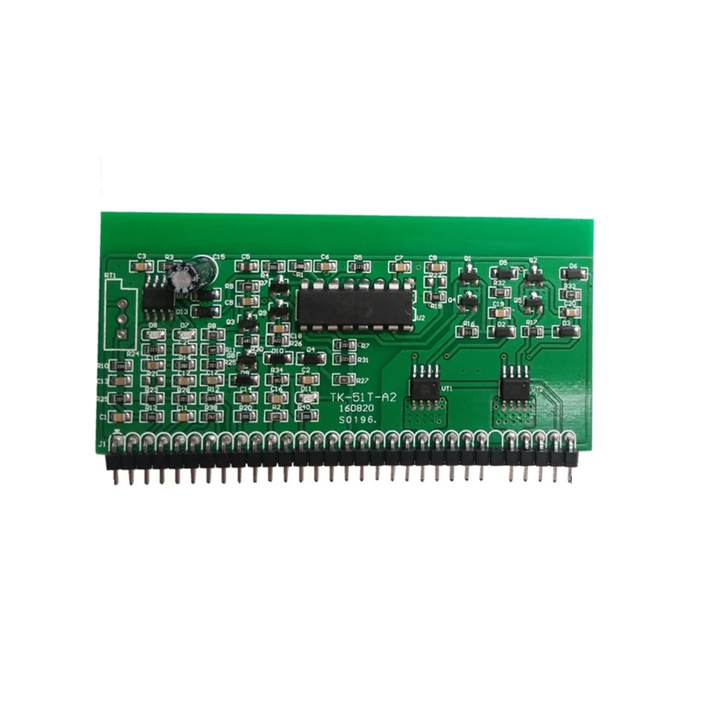
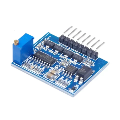
TK 51T-A2 PWM Driver Module 30Pin Inverter Welding Machine Control Board acts as a centralized, high-precision control unit engineered specifically for industrial inverter welding machines. This sophisticated daughterboard generates the vital pulse-width modulation (PWM) signals required to drive high-power IGBT or MOSFET inverter topologies safely and efficiently. Consequently, it stabilizes the welding arc and optimizes power delivery under fluctuating load conditions. The module relies on a dense 30-pin interface to handle power delivery, feedback loops, and protection monitoring simultaneously. Furthermore, its robust construction resists the severe electrical noise and thermal stress common to industrial workshop environments. Therefore, repairing or upgrading your machinery with this genuine replacement control board ensures consistent arc characteristics and restores original factory performance parameters.
Key Features:
- Precise PWM Generation: Delivers highly accurate pulse-width modulation waveforms to secure an exceptionally stable welding current and smooth arc control.
- Comprehensive Protection Circuits: Includes integrated monitoring hooks for over-current, over-voltage, and thermal overload conditions to safeguard the main inverter switches.
- High-Density 30-Pin Interface: Consolidates power inputs, feedback lines, error signals, and gate drive outputs onto a single, standardized 30-pin inline layout.
- Industrial-Grade Noise Immunity: Features strategic onboard filtering and a optimized multi-layer PCB layout; consequently, the board rejects high-frequency electromagnetic interference (EMI) from the welding arc.
- Pre-calibrated Tuning: Ships with factory-set potentiometer adjustments for critical timing constraints, which minimizes setup time during machinery overhauls.
Technical Specifications:
- Input Operating Voltage: 15 VDC (±10% dual rail or single rail depending on system configuration)
- Interface Form Factor: 30-Pin Male Header Inline Layout
- PWM Frequency Range: ≈ 20 kHz to 40 kHz (Optimized for standard industrial inverter topologies)
- Maximum Duty Cycle: ≈ 45% per channel (Includes dead-time insertion to prevent shoot-through currents)
- Output Drive Capability: Designed to interface with external push-pull current amplification driver stages
- Feedback Sensing Voltage: Configured for standard current transformer and shunt inputs (≤ 5 V peak inputs)
Mechanical Specifications:
- Form Factor: Vertical Plug-in Daughterboard Card
- Pin Connector Style: Single row, through-hole 30-pin standard male header strip
- Substrate Material: Flame-retardant FR-4 fiberglass reinforced epoxy
- Coating Protections: Features a moisture-resistant conformal coating to insulate against conductive metallic grinding dust.
Dimensions:
- Total Board Length: ≈ 82.5 mm
- Total Board Height: ≈ 45.0 mm
- Pin Center-to-Center Pitch: Standard 2.54 mm (0.1 inch) spacing
- Overall Module Thickness: ≈ 12.0 mm (Including protruding electrolytic capacitors and trimmer pots)
Pinout and Wiring:
- Pins 1 to 5 (Power Supply In): Receive regulated operating voltages, typically including +15V, −15V, and digital ground references.
- Pins 6 to 12 (Feedback Sensors): Accept current-transformer, voltage feedback, and thermal thermistor signals directly from the main transformer and output diodes.
- Pins 13 to 20 (Control and Adjustments): Connect to external front-panel potentiometer controls for setting the current target, arc force, and hot-start parameters.
- Pins 21 to 25 (PWM Driver Outputs): Route the complementary high-speed PWM gate drive signals to the primary inverter driver stage boards.
- Pins 26 to 30 (Status and Protection): Link directly to front-panel error LEDs, standby switches, and remote control triggers.
- Wiring Note: However, always verify the manufacturer-specific pin matching schema of your primary mainboard before powering on, as minor variations exist across factory production runs.
Datasheet Reference:
- Download Core UC3525/SG3525 PWM Controller IC Datasheet
Commonly Used in:
- Inverter Welding Machines: Serving as the main controller logic inside multi-board IGBT welding architectures.
- Heavy Industrial Overhauls: Acting as a universally compatible replacement control card for repairing generic import welders.
- DIY Power Inverters: Providing a robust base timing board for building high-power custom induction heating setups.
Applications:
- Shielded Metal Arc Welding (SMAW): Regulates stable constant-current curves required for stick welding applications.
- Gas Tungsten Arc Welding (GTAW): Offers precise low-current pulse timing required for fine-scale TIG operations.
- Gas Metal Arc Welding (GMAW): Delivers steady power control loops necessary for consistent wire-feed MIG welding execution.
Equivalent Models:
- TK 51T-A1: An older iteration featuring slightly modified feedback input sensitivities, which users can adapt through minor recalibrations.
- ZX7-200 Control Board: A functionally identical 30-pin modular timing driver card shared widely across generic 200A inverter welding topologies.
- SG3525 30-Pin Controller Card: A generic commercial equivalent built around the identical pulse-width modulation platform.
Package Includes:
- 1 x TK 51T-A2 PWM Driver Module 30Pin Inverter Welding Machine Control Board
Additional information
| Weight | 50 g |
|---|
Questions and Answers
No questions have been asked about this product yet. Be the first!
Ask a Question
You must be logged in to ask a question.
Log in
Reviews
There are no reviews yet.