
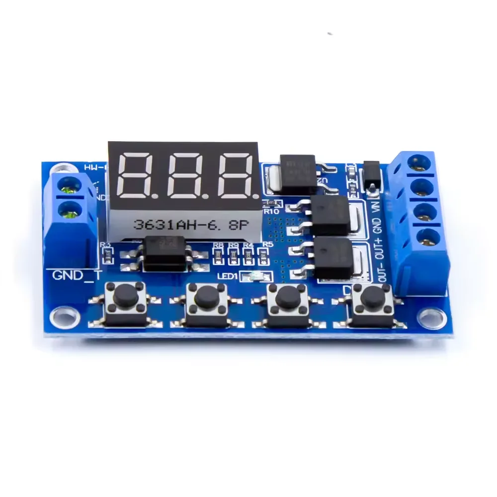
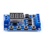
XY-J04 Trigger Cycle Timer Delay Switch Dual MOSFET Control Board is a programmable digital delay timer and PWM-capable solid-state power switch module equipped with dual parallel N-channel power MOSFETs and a 3-digit LED display. Operating across a wide 5V to 36V DC load range at up to 15A continuous current (400W) and up to 30A with auxiliary heatsinking, it replaces mechanical relays with silent, arc-free, microsecond-fast electronic switching across multiple programmable timing modes (On-Delay, Off-Delay, Infinite/Finite Cycle Loop).
Key Features:
- Dual Parallel High-Power MOSFETs (15A / 400W): Low-RDS(on) parallel MOSFET output stage switches 5V–36V DC loads up to 15A continuously at room temperature (up to 30A with extra cooling) with zero mechanical contact wear.
- Multiple Programmable Timer Modes (P1–P4): Supports delayed turn-on, delayed turn-off, one-shot pulse, and infinite/counted cyclic ON/OFF looping with timing adjustable from 0.1 seconds to 999 minutes.
- Optocoupler-Isolated Trigger Input: Accepts high-level (3.0V–24V DC) trigger pulses from microcontrollers, PLC outputs, limit switches, or proximity sensors with optical noise immunity.
- 3-Digit LED Display & 4-Button Interface: Allows intuitive programming of OP (On-Time), CL (Off-Time), and LOP (Cycle Count) parameters stored in non-volatile EEPROM memory.
- Emergency STOP Key & Sleep Mode: Front STOP button immediately disables MOSFET conduction during emergencies and toggles display auto-sleep mode.
Technical Specifications:
- Model: XY-J04 / XY-MOS Digital Delay Timer MOSFET Switch
- Operating & Load Voltage: 5.0V to 36.0V DC
- Continuous Output Current: 15A (Up to 400W at room temperature; up to 30A with heatsink)
- Trigger Signal Voltage: High-Level Trigger (3.0V to 24.0V DC; Trigger GND can be isolated from Power GND)
- Timing Range: 0.1 Seconds (Min) to 999 Minutes (Max) Continuously Configurable
- Quiescent Current: ~20 mA (Operating) / ~15 mA (Display Sleep)
- Service Life: Unlimited Solid-State Switching Cycles | Operating Temp: -40°C to +85°C
Mechanical Specifications:
- PCB Material: FR-4 Double-Sided Blue Fiberglass Board
- Terminals: 6-Pin Barrier Screw Terminal Block (VIN+, VIN-, OUT+, OUT-, Trigger+, Trigger-)
- User Interface: 3-Digit 7-Segment Red LED Display + 4 Tactile Push Buttons (STOP, SET, UP, DOWN)
Dimensions:
- Length: 60 mm
- Width: 34 mm
- Height: 12 mm
- Weight: ~22 g
Pinout and Wiring:
- VIN+ / VIN-: Connect 5V–36V DC main power supply.
- OUT+ / OUT-: Connect 5V–36V DC load (Note: OUT+ is internally tied to VIN+; the dual MOSFETs switch the low side OUT-).
- Trigger / GND_T: Apply 3V–24V DC trigger pulse to initiate the programmed timing sequence.
- Programming: Long-press SET (2s) to select mode P1.1–P4, short-press SET to set OP/CL/LOP values, and long-press SET again to save.
Datasheet Reference:
- Architecture: Non-Volatile MCU Timer + Optocoupler Input + Dual Parallel Low-Side N-Channel Power MOSFETs
Commonly Used in:
- Automated Solenoid Valve, Pump, and Actuator Cycle Timers
- High-Current DC Motor & Heater Intermittent Controllers
- Automotive Daytime Running Light (DRL) & Horn Delay Modules
- Endurance Burn-In & Life-Cycle Testing Rigs
Applications:
- Cycles DC solenoid valves, peristaltic pumps, or linear actuators ON and OFF at high frequencies where mechanical relays would weld shut or wear out.
- Triggers a timed 0.1s–999m output run whenever an IR sensor, push button, or PLC output fires.
- Automates repetitive component fatigue testing with a programmable cycle counter (LOP = 1 to 999 cycles or `—` infinite).
Equivalent Models:
- DC 5V-36V 15A 400W Switch Large Power MOSFET Module: Dual-MOSFET PWM trigger board without the onboard programmable timer MCU/display.
- 4V-60V DC 10A High-Power MOSFET Trigger Drive Switch Module: Higher-voltage (up to 60V) single/dual MOSFET trigger switch.
Package Includes:
- 1 × XY-J04 Trigger Cycle Timer Delay Switch Dual MOSFET Control Board





Reviews
No reviews yet. Be the first to share your experience!