


Frequency Adjustable Pulse Generator Module NE555
₹30.00
Frequently Bought Together
Frequency Adjustable Pulse Generator Module NE555 is a versatile and compact timing solution designed to produce reliable square wave signals for various electronic control applications. Built around the industry-standard NE555 timer IC, this module allows users to generate a steady stream of pulses with adjustable frequency and duty cycle. Consequently, it serves as an excellent clock source for stepper motor drivers, PWM controllers, and DIY electronics projects. The board features multi-turn potentiometers and a frequency range jumper, which provide precise control over the output characteristics. Furthermore, its wide input voltage range ensures compatibility with both 5V and 12V logic systems. Therefore, you can easily integrate this module into your design to act as a stable signal generator without needing complex microcontroller programming.
Key Features:
- Adjustable Frequency Range: The onboard 4-position jumper allows users to select between four distinct frequency bands, ranging from 1Hz to 200kHz.
- Dual Potentiometer Control: Features independent trim pots to fine-tune the output frequency and the duty cycle, providing maximum flexibility for pulse-width modulation.
- Visual Output Indicator: Includes an onboard LED that flashes at low frequencies, allowing you to visually verify the pulse output at a glance.
- Standard NE555 Core: Utilizes the highly reliable NE555 timer chip, known for its temperature stability and robust performance in timing circuits.
- Buffered Output: The module produces a clean square wave output capable of driving small loads or providing a trigger signal to power transistors and ICs.
Technical Specifications:
- Input Voltage (VCC): 5V to 15V DC
- Input Current: ≥ 100 mA
- Output Amplitude: 4.2V V-PP to 11.4V V-PP (Depending on input voltage)
- Maximum Output Current: ≈ 15 mA (at 5V) to 35 mA (at 12V)
- Frequency Bands: 1Hz–50Hz, 50Hz–1kHz, 1kHz–10kHz, 10kHz–200kHz
- Duty Cycle Adjustment: 50% to 100% (Adjustable)
Mechanical Specifications:
- PCB Material: High-quality FR4 Glass Fiber
- Mounting Holes: 4 x 3 mm diameter holes for secure chassis mounting
- Connector Type: 3-pin male header (GND, OUT, VCC)
- Potentiometer Type: Multi-turn precision cermet trim pots
Dimensions:
- Board Length: ≈ 31 mm
- Board Width: ≈ 22 mm
- Total Height: ≈ 15 mm
- Weight: ≈ 7 g
Pinout and Wiring:
- Pin 1 (GND): Connect this pin to the negative terminal of your power supply.
- Pin 2 (OUT): The square wave pulse output pin. Connect this to your load or oscilloscope.
- Pin 3 (VCC): Power input pin. Connect to a DC source between 5V and 15V.
- Note: However, ensure the input voltage does not exceed 15V to prevent damaging the NE555 IC.
Datasheet Reference:
Commonly Used in:
- Stepper Motor Controllers: Providing the step pulses required to drive motor drivers like the A4988 or DRV8825.
- LED Dimming Circuits: Acting as a PWM source to control the brightness of DC LED strips.
- Audio Tone Generators: Creating basic audible square waves for testing speakers or buzzers.
Applications:
- Clock Signal Generation: Providing a consistent clock pulse for digital logic gates and counters.
- DC Motor Speed Control: Serving as the base signal for PWM speed controllers when paired with a power MOSFET.
- Circuit Testing: Troubleshooting digital circuits by injecting a known pulse frequency into signal paths.
Equivalent Models:
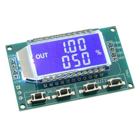
- XY-LPWM Module: A digital alternative featuring an LCD screen for frequency readout, however, it is more complex than the analog NE555 version.
- AD9833 DDS Module: A programmable waveform generator, although it requires a microcontroller for operation.
- LM358 PWM Module: Uses an op-amp for pulse generation, often providing a different duty cycle range.
Package Includes:
- 1 x Frequency Adjustable Pulse Generator Module NE555
Additional information
| Weight | 5 g |
|---|---|
| Dimensions | 25 × 13 × 10 mm |
Questions and Answers
No questions have been asked about this product yet. Be the first!
Ask a Question
You must be logged in to ask a question.
Log in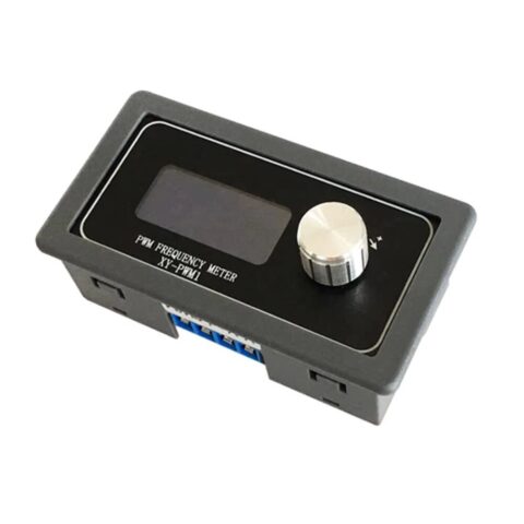


Reviews
There are no reviews yet.