
Roll over image to zoom in
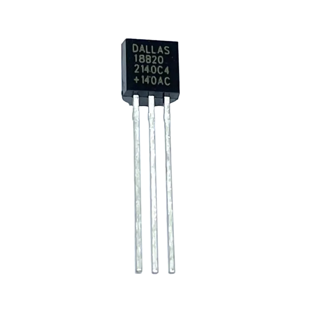
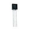
DS18B20 Digital Temperature Sensor TO-92
Save 0% ₹21.95₹22.00
You save
DS18B20 Digital Temperature Sensor (TO-92) reads temperature digitally and delivers a precise, easy-to-integrate solution for embedded and IoT projects. Designers use it for environmental monitoring, thermostats, and data-logging where a single-wire digital interface and wide temperature range simplify wiring and calibration.
Key Features:
- Digital 1-Wire Interface: Communicates over a single data line. Multiple sensors share one bus using unique 64-bit ROM codes.
- Wide Temperature Range: Measures from −55 °C to +125 °C for harsh and common environments.
- High Accuracy: Typical ±0.5 °C accuracy from −10 °C to +85 °C for many applications.
- Adjustable Resolution: Selectable 9-bit to 12-bit conversion resolution to trade speed for precision.
- Parasitic or External Power: Operates with a dedicated VDD or in parasite-power mode to simplify wiring.
- Compact TO-92 Package: Easy to mount on breadboards and PCBs for prototypes and small runs.
Technical Specifications:
- Supply Voltage (VDD): 3.0 V to 5.5 V (external) or parasite-power option via data line.
- Temperature Range: −55 °C to +125 °C.
- Accuracy: Typically ±0.5 °C from −10 °C to +85 °C; see datasheet for full error table.
- Resolution: Configurable 9-bit to 12-bit (0.5 °C to 0.0625 °C step).
- Conversion Time: Up to 750 ms for 12-bit conversion (shorter for lower resolution).
- Standby Current: Sub-µA standby; active conversion current typically ~1 mA (refer to datasheet for exact figures).
- Interface: Maxim/Dallas 1-Wire protocol; unique 64-bit ROM ID per device.
- Alarm Function: Programmable high/low temperature alarm registers for autonomous alerts on the bus.
Mechanical Specifications:
- Package: TO-92 plastic through-hole encapsulation.
- Body Material: Molded epoxy suitable for standard electronic environments.
- Lead Finish: Tin-plated leads compatible with standard soldering processes.
- Mounting: Through-hole for PCB or use in-wire harness with heat-shrink for simple installations.
Dimensions:
- TO-92 Typical Body: Body width ~4.5 mm, height ~5.0–6.5 mm (varies by manufacturer). Check mechanical drawing for precise values.
- Lead Spacing and Length: Standard TO-92 lead spacing; trim leads for PCB insertion or wire connections as required.
Pinout and Wiring:
- Pin 1 (left): GND (connect to system ground). When you face the flat side of the TO-92 body with leads down, this is the left pin.
- Pin 2 (middle): DQ (1-Wire data line). Use a pull-up resistor (typically 4.7 kΩ for 3.3–5 V systems). The device can run in parasite power mode using this pin.
- Pin 3 (right): VDD (3.0–5.5 V) when not using parasite power.
- Wiring note: Place the pull-up resistor close to the controller. Add decoupling on VDD for noisy environments. For long buses, use lower pull-up resistance or bus master buffer for reliability.
Datasheet Reference:
- Download the official DS18B20 datasheet from Maxim Integrated (now Analog Devices) for electrical characteristics, timing diagrams, ROM commands, and application circuits.
Applications:
- Environmental Monitoring: Integrate into weather stations and HVAC sensing systems.
- IoT and Data Logging: Use in distributed sensor networks and single-wire daisy-chained deployments.
- Thermostats and Appliances: Implement temperature control and safety cutouts.
- Industrial and Automotive Prototyping: Employ in test rigs where wide temperature range and unique IDs matter.
Equivalent Models:
- DS18S20: Earlier 1-Wire temperature sensor with lower native resolution; use if legacy compatibility is required.
- MAX31820: Other Maxim/Analog Devices 1-Wire temperature variants; verify specs before substitution.
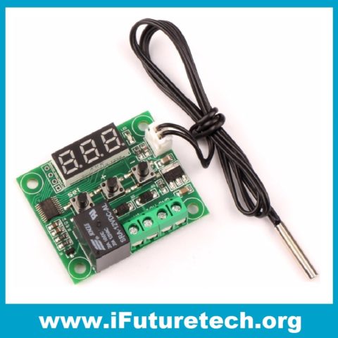
- Waterproof variants: Stainless steel probe versions with same DS18B20 die for immersion sensing applications.
Package Includes:
- 1 x DS18B20 Digital Temperature Sensor in TO-92
Additional information
| Weight | 1 g |
|---|

Reviews
There are no reviews yet.