

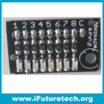
DC 5V-12V 8-Bit LED Indicator Module Board is an 8-channel breadboard-friendly visual indicator board featuring 8 individual high-brightness LEDs driven through onboard current-limiting resistors. Designed to operate across a wide input voltage from 5V to 12V DC with active-high/active-low configurable headers, it provides a clean, clutter-free way to visualize 8-bit bus states, binary counters, and microcontroller GPIO outputs without a tangle of individual resistors and jumpers.
Key Features:
- 8 Independent LED Channels: 8 bright 3mm/5mm LEDs neatly aligned to display an entire byte (8 bits) of digital data simultaneously.
- Wide Operating Voltage (5V–12V DC): Onboard current-limiting resistors allow safe operation directly from 5V, 9V, or 12V power rails.
- Common Bus Interface: Single common ground / common anode bus pin minimizes required wiring to the host microcontroller.
- Eliminates Breadboard Resistor Clutter: Pre-soldered onboard ballast resistors replace 8 discrete resistors on solderless breadboards.
- Direct Microcontroller GPIO Connection: Compatible with Arduino UNO digital pins D0–D7, Port B/D registers, Raspberry Pi, and 8051 trainers.
- Compact In-Line Layout: Straight pin header design allows clean plugging along breadboard edge power rails.
Technical Specifications:
- Operating Voltage: 5V to 12V DC
- Current Consumption: Approximately 10 mA to 15 mA per LED (~100 mA total with all LEDs lit)
- LED Count: 8 individual high-efficiency colored LEDs (Red / Green / Blue / Yellow)
- Ballast Resistor Value: Onboard SMD current-limiting resistors (typically 470Ω to 1kΩ)
- Control Logic: Common Cathode (active-HIGH) / Common Anode (active-LOW) selectable wiring
- Connector Type: Standard 1×9 or 1×10 male pin header (2.54mm pitch)
- Operating Temperature: -20°C to +75°C
Mechanical Specifications:
- Form Factor: Linear 8-channel indicator bar layout
- PCB Construction: Double-sided FR4 fiberglass board with red protective solder mask
- Mounting: Direct solderless breadboard insertion or chassis bracket mounting
- Header Type: Right-angle or straight 2.54mm male header
- Weight: Approximately 6.0 g
Dimensions:
- Overall Length: 55.0 mm
- Overall Width: 15.0 mm
- Overall Height: 10.0 mm
Pinout and Wiring:
- Pins D1 to D8: Connect to microcontroller digital output GPIO pins for controlling channels 1 through 8
- GND / VCC: Common power reference rail (connected to microcontroller Ground or VCC depending on board configuration)
Datasheet Reference:
- Refer to the 8-Bit LED Bar Module engineering schematic and current-limiting resistor calculations for dissipation tables and port register mapping in AVR C and Arduino IDE.
Commonly Used in:
- Educational microcontroller training kits demonstrating 8-bit binary counters and shift registers
- Logic state visualizers for parallel data buses and address lines in retrocomputing projects
- Visual status bar indicators for battery level, audio volume, and sensor thresholds
- Classroom computer architecture courses teaching byte manipulation and register visualization
Applications:
- 8-bit binary counter display
- Microcontroller GPIO state visualizer
- Digital bar graph and level indicator
- Logic analyzer bus state monitor
- STEM classroom digital electronics trainer
Equivalent Models:
- 8-Channel LED Bar Graph Display Module
- 10-Segment LED Bargraph Display
- 74HC595 8-Bit Shift Register LED Board
- Keyestudio 8-Bit LED Module
Package Includes:
- 1 × DC 5V-12V 8-Bit LED Indicator Module Board




Reviews
No reviews yet. Be the first to share your experience!