
Roll over image to zoom in
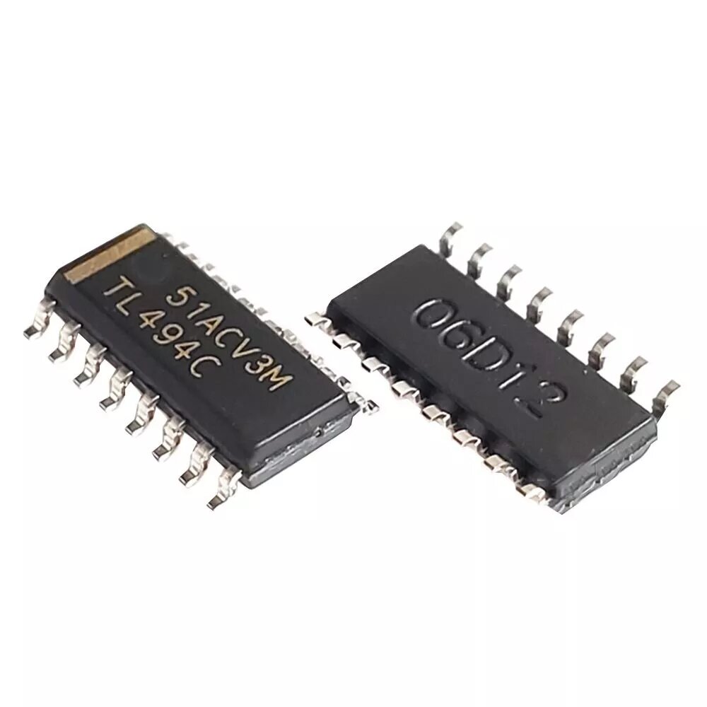
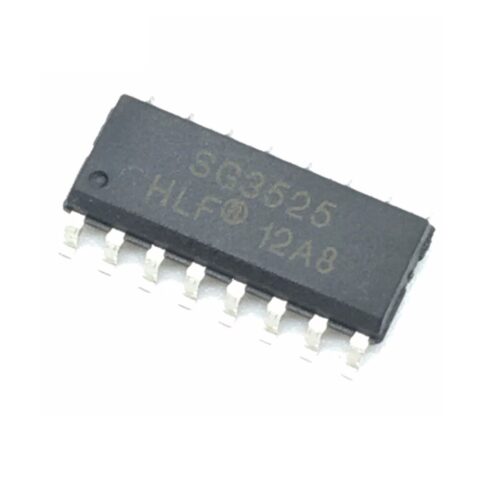
TL494 Pulse Width Modulation Controller IC SOP-16
₹15.00
TL494 Pulse Width Modulation (PWM) Controller IC stands as a foundational and highly reliable chip for designing switching power supplies and DC-DC converters. Engineers have consistently chosen this integrated circuit for decades because it provides all the necessary control logic to build a fixed-frequency PWM system. The TL494 features an on-chip oscillator, error amplifiers, a dead-time control comparator, and flexible output control. Its dual-output transistors can operate in either push-pull or single-ended configurations, giving you immense versatility in your circuit design. If you are building robust, efficient, and cost-effective power electronics, the TL494 offers a proven and time-tested solution.
Key Features:
- Complete PWM Control Circuit: Integrates all essential building blocks, including a voltage reference, oscillator, error amplifiers, and output drivers, into a single package.
- Dual Error Amplifiers: Two internal operational amplifiers allow for robust control loops, enabling simultaneous voltage and current limit regulation.
- Dead-Time Control: An adjustable dead-time control comparator prevents shoot-through current in push-pull applications, thereby enhancing the power supply’s efficiency and reliability.
- Uncommitted Output Transistors: The dual output transistors are uncommitted, offering flexibility to configure the chip for either single-ended (forward converters) or push-pull (full-bridge/half-bridge) topologies.
- Wide Operating Voltage: You can power the chip with a supply voltage up to 40V, accommodating various power system standards.
- External Clock Synchronization: The oscillator can be synchronized with an external clock, useful for applications requiring master/slave operation or frequency interlocking.
Technical Specifications:
- Operating Voltage (VCC): 7V to 40V
- Reference Voltage (VREF): 5.0V $\pm$5% (internal)
- Output Current (IOUT): Up to 200 mA (sink or source) per transistor
- Oscillator Frequency Range: 1 kHz to 300 kHz (adjustable via external R and C)
- Duty Cycle Control: 0% to 100%
- Package Type: SOP-16 (Small Outline Package)
Mechanical Specifications:
- Pin Count: 16 Pins
- Mounting: Surface Mount Device (SMD)
- Material: Plastic molded package.
Dimensions:
- Length (Body): ~9.9 mm
- Width (Body): ~3.9 mm
- Pin Pitch (Spacing between pins): 1.27 mm (0.05 in)
Pinout and Wiring:
- Pin 1 (1IN+), 2 (1IN-): Non-Inverting and Inverting inputs for Error Amplifier 1. Used for voltage feedback.
- Pin 3 (FB): Feedback input. Connects to the output of the two error amplifiers.
- Pin 4 (DTC): Dead-Time Control. Connect to GND for minimum dead time (max duty cycle) or adjust with a voltage divider.
- Pin 5 (CT), 6 (RT): Timing Capacitor and Resistor. These external components set the oscillator frequency.
- Pin 7 (GND): Ground.
- Pin 8 (C1), 9 (E1): Collector and Emitter of Output Transistor 1.
- Pin 10 (C2), 11 (E2): Collector and Emitter of Output Transistor 2.
- Pin 12 (VCC): Supply voltage input.
- Pin 13 (OE): Output Enable/Control. Connect to VCC for push-pull operation, or to GND for single-ended/parallel operation.
- Pin 14 (VREF): 5V Reference Voltage output.
- Pin 15 (2IN-), 16 (2IN+): Inverting and Non-Inverting inputs for Error Amplifier 2. Often used for current sensing/limiting.
- Wiring Note: Always select RT and CT values carefully to set the desired switching frequency. The OE pin dictates the output stage configuration (push-pull or single-ended).
Datasheet Reference:
Commonly Used in:
- ATX Power Supplies: Historically a core component in computer power supplies.
- Inverters: Used in DC-AC power inverters to generate the required high-frequency switching signal.
- Battery Chargers: Provides the PWM control necessary for efficient battery charging circuits.
Applications:
- Switching Power Supplies (SMPS): Control the switching action of MOSFETs or BJTs in flyback, forward, and push-pull converters.
- DC-DC Converters: Regulate output voltage in automotive and industrial buck/boost converter designs.
- Motor Control: Use the generated PWM signal to control the speed and torque of DC motors.
Equivalent Models:
- KA7500: A functionally equivalent IC from Fairchild/ON Semiconductor.
- UC384x Series: A family of single-ended (not push-pull) current-mode PWM controllers often used in flyback converters.
Package Includes:
- 1 x TL494 Pulse Width Modulation Controller IC SOP-16
Additional information
| Weight | 1 g |
|---|
Reviews
There are no reviews yet.