ADS1115 I2C 16 BIT ADC 4 CHANNEL MODULE
₹235.00
You save
- PROGRAMMABLE DATA RATE: 8SPS to 860SPS
- It has an Internal low-drift voltage reference
- Internal Oscillator.
- Internal PGA.
- I2C INTERFACE : Pin-Selectable Addresses.
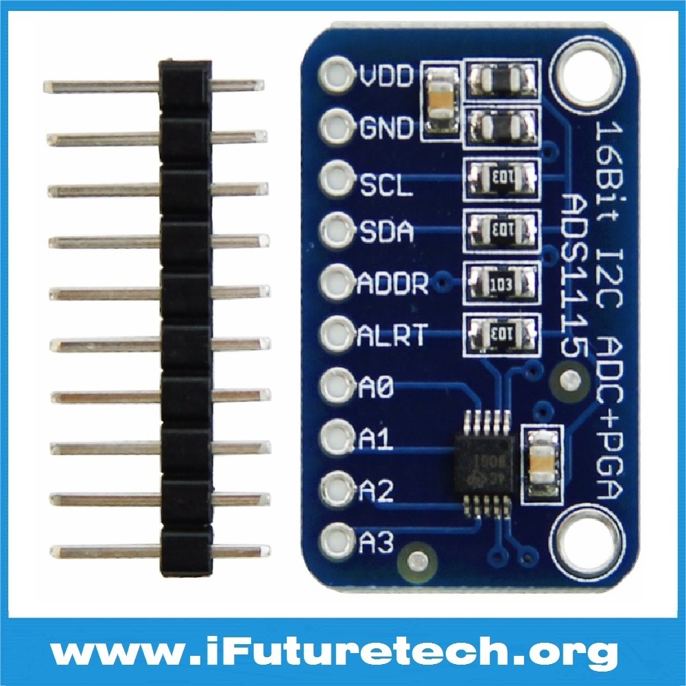
- This board/chip uses I2C 7-bit addresses between 0x48-0x4B, selectable with jumpers
ADS1115 I2C 16 Bit ADC 4 Channel Module is a high-precision analog-to-digital converter (ADC) that provides 16-bit resolution and supports up to 4 single-ended or 2 differential inputs. Based on the ADS1115 IC from Texas Instruments, this module is ideal for applications requiring high-resolution analog-to-digital conversion with a simple I2C interface for communication with microcontrollers like Arduino, Raspberry Pi, and ESP32.
Key Features of ADS1115 I2C 16 Bit ADC 4 Channel Module:
-
- 16-Bit Resolution: Provides high-precision analog-to-digital conversion with 16-bit resolution.
- 4 Input Channels: Can be configured as 4 single-ended or 2 differential inputs for flexible usage.
- Programmable Gain Amplifier (PGA): Adjustable gain from ±0.256V to ±6.144V.
- I2C Interface: Simplifies communication with microcontrollers and SBCs, providing a faster data rate.
- Low Power Consumption: Operates with low power, suitable for battery-operated devices.
- Compact Design: Small size makes it ideal for integration into space-constrained projects.
Technical Specifications of ADS1115 I2C 16 Bit ADC 4 Channel Module:
-
- Resolution: 16 bits
- Operating Voltage: 2.0V to 5.5V
- Input Voltage Range: ±0.256V to ±6.144V (adjustable via PGA)
- Input Channels: 4 single-ended or 2 differential
- Data Rate: Configurable up to 860 samples per second
- Interface: I2C (up to 3.4MHz)
- Current Consumption: 150µA during conversion
- Dimensions: Approximately 20mm x 15mm
Mechanical Specifications of ADS1115 I2C 16 Bit ADC 4 Channel Module:
-
- Dimensions: 20mm x 15mm
- Mounting Holes: None, but compact design allows for soldering onto PCBs or breadboards.
- Weight: Approximately 2 grams
- PCB Material: FR4, standard green solder mask with clear silkscreen labels.
Schematic Diagram, Connection, Wiring, and Pinout of ADS1115 I2C 16 Bit ADC 4 Channel Module:
-
- Schematic Diagram: Features the ADS1115 IC as the core, connected to power, ground, and I2C lines for communication. Input pins are routed for analog signals.
- Connection Steps:
- 1. Connect the VCC pin to 3.3V or 5V power supply.
- 2. Connect the GND pin to ground.
- 3. Connect the SCL and SDA pins to the I2C clock and data lines on the microcontroller.
- 4. Attach analog inputs to the A0, A1, A2, and A3 pins as needed.
- Pinout:
- VCC: Power supply input (3.3V or 5V)
- GND: Ground
- SCL: I2C Clock Line
- SDA: I2C Data Line
- A0, A1, A2, A3: Analog inputs
- ADDR: I2C address configuration pin
- ALRT: Alert/Ready output pin
Applications of ADS1115 I2C 16 Bit ADC 4 Channel Module:
-
- Sensor Integration: Interface with analog sensors for precise data acquisition.
- Battery Monitoring: Measure battery voltage and current accurately.
- Industrial Control: Use in applications requiring multiple analog inputs.
- IoT Projects: Ideal for adding ADC functionality in IoT systems.
- DIY Electronics: Perfect for hobby projects needing enhanced analog input capability.
Equivalent Models of ADS1115 I2C 16 Bit ADC 4 Channel Module:
-
- GY-ADS1115: A similar ADC module with 16-bit resolution.
- MCP3008: An SPI-based ADC with 10-bit resolution and 8 channels.
Datasheet:
Keywords for ADS1115 I2C 16 Bit ADC 4 Channel Module:
-
- ADS1115
- 16-bit ADC Module
- I2C ADC
- Analog-to-Digital Converter
- Precision ADC
Package Includes:
-
- 1 x ADS1115 I2C 16 Bit ADC 4 Channel Module
Additional information
| Weight | 5 g |
|---|---|
| Dimensions | 28 × 18 × 3 mm |

Reviews
There are no reviews yet.